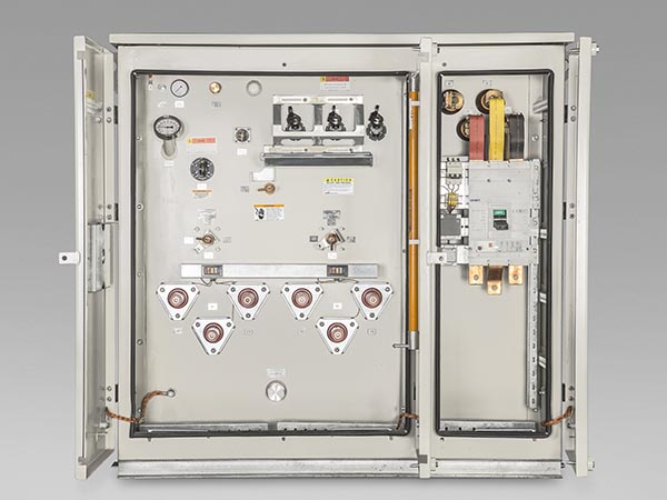
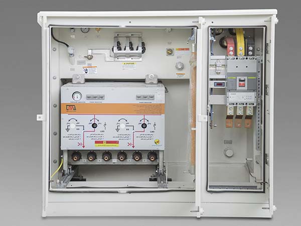
Pad mounted compact substation
Pad mounted compact substations are produced in two full-oil and gas-oil types and include the main tank of the substation, medium voltage and low voltage tank. The design of these products is in a way that all accesses for the operator are from one side during operation.
For special orders, design and analysis is done according to the customer's needs considering the temperature and Height above sea level.
Due to their compactness and placing on a concrete foundation, these types of substations enable installation and operation in the shortest possible time for project construction and electrification.
Fully oiled pad mounted substation
In full-oil compact substations, all equipment, including transformers, switching and protective equipment, are placed in a common tank with oil insulation.

Features:
- Separate access to both medium-voltage and low-voltage equipment
- Three layers of color coating (zinc rich - epoxy – polyurethane)
- Ease of transportation due to low weight and reduced dimensions
- Effectively reduced losses in the medium voltage grid
- Requires small space for installation and minimizing land costs
- Low service and maintenance costs
- Different arrangements (radial and ring) based on customer's needs
- Possibility to be designed for different weather conditions
- Certified by most well-known international institutes such as KERI in South Korea, CPRI in India and Niroo Research Institute (NRI)
- Substation design according to ANSI CS7.12.30 standards
- Possibility to be designed and produced up to 63 KV voltage level
- Installing measuring equipment on the MV and LV side
- Automation capability
| Technical Specification for Pad-Mounted Transformer | ||||||
| Power (KVA) | MV Switchgear | Bay-O-Net Fuse (A) | MCCB (A) | H (mm) | W (mm) | D (mm) |
| 100 | OIS | 3 | 200 | 1440 | 1780 | 1490 |
| 160 | OIS | 8 | 250 | 1440 | 1780 | 1490 |
| 200 | OIS | 8 | 400 | 1440 | 1780 | 1490 |
| 250 | OIS | 8 | 400 | 1440 | 1780 | 1490 |
| 315 | OIS | 15 | 630 | 1440 | 1780 | 1490 |
| 400 | OIS | 15 | 630 | 1555 | 1785 | 1770 |
| 500 | OIS | 15 | 800 | 1555 | 1785 | 1770 |
| 630 | OIS | 25 | 1000 | 1555 | 1785 | 1850 |
| 800 | OIS | 25 | 1250 | 1630 | 1990 | 1950 |
| 1000 | OIS | 40 | 1600 | 1630 | 1990 | 2050 |
| Power (KVA) | Voltage (MV/LV) KV | Frequency (Hz) | Vector Group | No Load Loss (W) | Load Loss 75oC (W) | Power Frequency (KV) | Lighting Impulse (KV) | MV Switchgear | Bay-O-Net Fuse (A) | MCCB (A) |
| 100 | 20/0.4 | 50 | Dyn5 | 210 | 1550 | 50/3 | 125 | OIS | 3 | 200 |
| 160 | 20/0.4 | 50 | Dyn5 | 300 | 2320 | 50/3 | 125 | OIS | 8 | 250 |
| 200 | 20/0.4 | 50 | Dyn5 | 355 | 2760 | 50/3 | 125 | OIS | 8 | 400 |
| 250 | 20/0.4 | 50 | Dyn5 | 425 | 3250 | 50/3 | 125 | OIS | 8 | 400 |
| 315 | 20/0.4 | 50 | Dyn5 | 500 | 3850 | 50/3 | 125 | OIS | 15 | 630 |
| 400 | 20/0.4 | 50 | Dyn5 | 610 | 4600 | 50/3 | 125 | OIS | 15 | 630 |
| 500 | 20/0.4 | 50 | Dyn5 | 720 | 5450 | 50/3 | 125 | OIS | 15 | 800 |
| 630 | 20/0.4 | 50 | Dyn5 | 800 | 6750 | 50/3 | 125 | OIS | 25 | 1000 |
| 800 | 20/0.4 | 50 | Dyn5 | 940 | 8500 | 50/3 | 125 | OIS | 25 | 1250 |
| 1000 | 20/0.4 | 50 | Dyn5 | 1100 | 10500 | 50/3 | 125 | OIS | 40 | 1600 |
| 1250 | 20/0.4 | 50 | Dyn5 | 1300 | 13200 | 50/3 | 125 | OIS | 40 | 2000 |
| 1600 | 20/0.4 | 50 | Dyn5 | 1700 | 16900 | 50/3 | 125 | OIS | 50 | 2500 |
| 2000 | 20/0.4 | 50 | Dyn5 | 2055 | 21000 | 50/3 | 125 | OIS | 65 | 3200 |
Oil-gas pad mounted transformers
Oil-gas pad mounted transformers using all types of switching and protective equipment are produced with minimal dimensions according to the customer's needs.
In this type of substation, the switching and protective equipment including gas switches and fuses, are connected to the main substation tank by special bushings.

Features:
- Increasing the power of maneuver and utilizing in high maneuverability points in the distribution network
- Three layers of color coating (zinc rich - epoxy – polyurethane)
- IP65 for GIS switching equipment
- IP42 for AIS switching equipment
- Possibility to be produced in all capacities
- Possibility to be produced with different arrangements of switches based on customer's needs
- On-site services and maintenance
- Possibility to be designed and produced up to 63 KV voltage level
- Installing measuring equipment on the MV and LV side
- Automation capability
| Technical Specification for Oil-Gas Pad-Mounted Transformer | ||||||
| Power (KVA) | MV Switchgear | HRC Fuse (A) | MCCB (A) | H (mm) | W (mm) | D (mm) |
| 100 | GIS | 10 | 200 | 1510 | 1880 | 1895 |
| 160 | GIS | 10 | 250 | 1510 | 1880 | 1895 |
| 200 | GIS | 16 | 400 | 1510 | 1880 | 1895 |
| 250 | GIS | 16 | 400 | 1510 | 1880 | 1895 |
| 315 | GIS | 16 | 630 | 1510 | 1880 | 1895 |
| 400 | GIS | 20 | 630 | 1510 | 1880 | 1955 |
| 500 | GIS | 25 | 800 | 1510 | 1880 | 1955 |
| 630 | GIS | 32 | 1000 | 1510 | 1880 | 2050 |
| 800 | GIS | 40 | 1250 | 1510 | 1880 | 2050 |
| 1000 | GIS | 40 | 1600 | 1510 | 1880 | 2100 |
| Power (KVA) | Voltage (MV/LV) KV | Frequency (Hz) | Vector Group | No Load Loss (W) | Load Loss 75oC (W) | Power Frequency (KV) | Lighting Impulse (KV) | MV Switchgear | HRC Fuse (A) | MCCB (A) |
| 100 | 20/0.4 | 50 | Dyn5 | 210 | 1550 | 50/3 | 125 | GIS | 10 | 200 |
| 160 | 20/0.4 | 50 | Dyn5 | 300 | 2320 | 50/3 | 125 | GIS | 10 | 250 |
| 200 | 20/0.4 | 50 | Dyn5 | 355 | 2760 | 50/3 | 125 | GIS | 16 | 400 |
| 250 | 20/0.4 | 50 | Dyn5 | 425 | 3250 | 50/3 | 125 | GIS | 16 | 400 |
| 315 | 20/0.4 | 50 | Dyn5 | 500 | 3850 | 50/3 | 125 | GIS | 16 | 630 |
| 400 | 20/0.4 | 50 | Dyn5 | 610 | 4600 | 50/3 | 125 | GIS | 20 | 630 |
| 500 | 20/0.4 | 50 | Dyn5 | 720 | 5450 | 50/3 | 125 | GIS | 25 | 800 |
| 630 | 20/0.4 | 50 | Dyn5 | 800 | 6750 | 50/3 | 125 | GIS | 32 | 1000 |
| 800 | 20/0.4 | 50 | Dyn5 | 940 | 8500 | 50/3 | 125 | GIS | 40 | 1250 |
| 1000 | 20/0.4 | 50 | Dyn5 | 1100 | 10500 | 50/3 | 125 | GIS | 40 | 1600 |
| 1250 | 20/0.4 | 50 | Dyn5 | 1300 | 13200 | 50/3 | 125 | GIS | 50 | 2000 |
| 1600 | 20/0.4 | 50 | Dyn5 | 1700 | 16900 | 50/3 | 125 | GIS | 80 | 2500 |
| 2000 | 20/0.4 | 50 | Dyn5 | 2055 | 21000 | 50/3 | 125 | GIS | 80 | 3200 |
